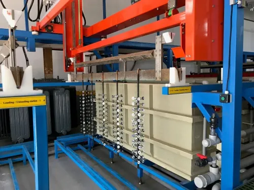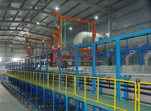
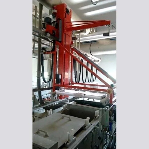
A PCB plating line is not automatically a complete PTH line: one may cover several copper-deposition and finishing stages, while the other must make drilled holes conductive and build a reliable copper barrel. By the end, you will be able to map the process sequence, compare deposition routes, specify controls for difficult aspect ratios, and judge reliability using evidence beyond surface thickness and continuity tests.
Key takeaways
- Treat PTH as a complete drilled-hole process, not only a copper-plating step.
- Control desmear, activation, chemistry, current density, agitation, and panel movement.
- Check high-aspect-ratio holes for voids, thin copper, and incomplete barrel coverage.
- Use microsections, thickness measurements, and thermal cycling to prove barrel reliability.
PCB plating line versus PTH line: where each process begins and ends
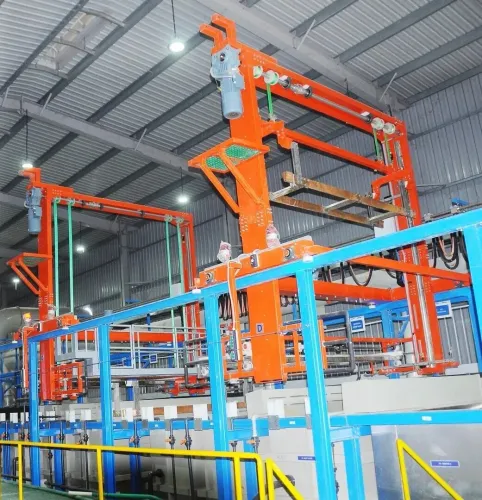
A PCB plating line is the broader system for depositing copper on board surfaces, patterns, or holes. A dedicated PTH line handles the complete route from hole drilling to inspection, converting an insulating drilled wall into a conductive barrel. The physical PTH line normally starts with desmear after drilling and ends with dried, inspected panels.
Resin smear can block contact with inner-layer copper, so desmearing requirements must be defined for the resin system, including permanganate, plasma and chemical alternatives.
| PCB plating line | Broad plating equipment for panel, pattern, or surface copper | Use when the process scope extends beyond through-holes |
|---|---|---|
| PTH line | Integrated hole-preparation, activation, electroless and electrolytic copper route | Use for plated through-holes requiring barrel continuity |
| Key boundary | Surface plating may begin with an already conductive panel; PTH must make the hole wall conductive first | Do not treat a general copper bath as a complete PTH process |
A complete PTH sequence contains these ordered operations:
- Hole drilling, followed by desmearing
- Hole-wall conditioning to prepare glass-resin surfaces
- Catalyst application, including palladium activation
- Accelerator treatment to expose usable catalytic sites
- Electroless copper deposition for initial continuity and adhesion
- Electrolytic copper build-up for economical barrel thickness
- Rinsing between stages, followed by drying
- Inspection for coverage, skips, voids and barrel continuity
Electroless copper is not the finished reliability layer. It enables electrical plating; electrolytic copper supplies most of the structural thickness. A line that omits either function is not a complete conventional PTH line.
How a drilled hole becomes an electrical connection
A plated through-hole becomes a circuit connection only after the prepared hole wall contacts each inner-layer copper land and receives a continuous conductive coating.
Electroless copper creates that first metallic path without external current; direct metallization uses direct metallization routes such as carbon or conductive polymer systems to make the wall conductive; electrolytic copper then uses current to build the structural barrel.
| Option | What it does | Main limitation |
|---|---|---|
| Electroless copper | Deposits a chemically reduced copper seed layer | It is not an economical finished reliability layer |
| Direct metallization | Applies a conductive carbon or polymer film before plating | The film must support adhesion and reliable electrolytic coverage |
| Electrolytic copper | Adds substantial copper under applied current | Poor distribution can leave the hole centre or knee thin |
Specify both the minimum local barrel-wall thickness and the process target. Use an electroless copper target of about 0.3–1.0 µm for continuity and adhesion, then set electrolytic copper build-up targets such as 20 µm for common Class 2 construction and 25 µm for more demanding Class 3 work.
Treat those figures as acceptance criteria only when your drawing or governing standard defines the measurement method.
Verify barrel continuity electrically, but do not accept a passing resistance reading as proof of construction. Take a metallographic microsection and inspect the minimum copper inside the barrel, knee and corner coverage, electroless-to-electrolytic interface, inner-layer connection, voids, cracks, nodules and separation.
The minimum local value matters more than the panel average; a single thin corner can become the failure site during thermal cycling.
Controls that determine coverage in high-aspect-ratio holes
A high aspect ratio, small hole diameter, and greater board thickness reduce copper reaching the centre and corners. The critical test is not tank-average thickness: local depletion inside the hole can leave a thin electroless deposit.
Control electroless chemistry as a system: copper concentration, pH, bath temperature, formaldehyde or reducing-agent control, complexant balance, dissolved oxygen, stabilizer level, and solution turnover. An imbalance can slow deposition inside the barrel while the bulk sample still passes analysis.
Acid-copper coverage depends on copper sulfate, sulfuric acid, chloride and organic additive balance, plus current density, bath temperature, agitation, anode condition, filtration and rectifier stability. Pulse and pulse-reverse plating improve distribution when the waveform matches the hole geometry; excessive agitation can trap air bubbles and create voids.
Solution circulation and throwing power depend on rack orientation, panel spacing, flow direction and eductor placement. Set agitation to exchange solution through the hole, not merely across the panel.
Rinse quality protects chemistry between stages. Use counter-current rinsing and drag-out management; contaminated or weakly flowing rinse tanks carry catalyst, acid, copper and organics into later baths.
| Panel plating | Copper covers the full panel before imaging | Control exposed area, current distribution and etch allowance across the board |
|---|---|---|
| Pattern plating | Copper builds mainly on circuitry and holes | Match resist thickness, current density and local solution flow to the circuit pattern |
| Either mode | Holes share the same barrel requirement | Record waveform, dwell time, temperature, analytical results, pump and filter status, and alarms |
Preventing PTH defects and proving barrel reliability
An ohmmeter can prove continuity while hiding an unreliable barrel. Prevent that false pass by controlling preparation, solution exchange, current distribution and mechanical stress, then accept the hole only against sectioned evidence: continuity proves a path, not sound copper around it.
- Use permanganate desmear to remove resin smear and expose the inner-layer copper land. Inspect for glass-fibre protrusion; inadequate treatment causes poor adhesion and later hole-wall cracking.
- Verify catalyst coverage across glass bundles and resin before electroless copper deposition. Gaps become skip plating or voids even when bath analysis passes.
- Use wetting-agent control, correct agitation direction and eductor flow to prevent trapped air bubbles. Set rack orientation and panel spacing for consistent solution exchange through the hole.
- Inspect anode bags, anode-to-cathode spacing and insoluble-anode shields. Measure busbar resistance and contact quality; a hot or intermittent contact creates burning, roughness and local thickness gradients.
Do not approve on average copper thickness. Microsection criteria require the minimum local barrel-wall thickness, continuous knee and corner coverage rather than thin copper in hole corners, a bonded electroless-to-electrolytic interface, and freedom from voids, nodules, separation and hole-wall cracking.
Judge copper ductility against laminate z-axis expansion, barrel geometry and thermal cycling; thicker copper alone cannot prove reliability.
Selecting and commissioning a line for the board you actually build
Compare the line with your actual panel size, hole aspect ratio, copper build, throughput and chemistry route—not the supplier’s maximum rectifier rating. High-aspect-ratio capability depends on solution exchange and throwing power, so inspect rack orientation, panel spacing, eductor placement and the risk of air entrainment trapping bubbles in holes.
| Option | Compare | Evidence to request |
|---|---|---|
| Horizontal conveyor | Throughput, contact stability and panel spacing | Sample panels at production speed |
| Vertical rack | Rack orientation, agitation pattern and loading flexibility | Coverage data for your largest aspect ratio |
| Pulse or pulse-reverse | Rectifier waveform, contact sensitivity and additive response | Coupon plating and cross-sections under the proposed recipe |
| Refurbished line | Equipment condition, controls replacement and future parts availability | Equipment refurbishment scope, test records and service terms |
Commission with a production-representative panel, not a flat witness coupon alone. Lock recipes against incorrect dwell time, transfer delay, current density, temperature and conductivity; record pump and filter status, alarms and every operator intervention.
AK Automation Systems can be useful to involve when equipment refurbishment must be matched with installation and service support rather than treated as a controls-only upgrade.
Your acceptance file should correlate each run with traceability data: analytical results and solution analysis, Hull-cell testing, coupon plating, current and voltage trends, rectifier waveform, alarm history and metallographic microsections. Final continuity alone can miss local voids and latent barrel cracks; tank titration alone can miss additive imbalance or depletion inside a high-aspect-ratio hole.
Reject commissioning until failed panels can be tied to a chemistry, transport, contact or process record.
Frequently asked questions
What is the difference between a PCB plating line and a PTH line?
A PCB plating line is the broader system for depositing copper on board surfaces, patterns, or holes. A PTH line covers the route that converts drilled, insulating hole walls into conductive barrels, beginning with desmear and ending with drying and inspection.
How does a drilled hole become an electrical connection?
After drilling, desmear removes resin residue and exposes a clean hole wall. Conditioning, catalysation, acceleration, and electroless copper create a conductive layer, followed by electrolytic copper plating that builds the barrel thickness and connects the board layers.
Which controls affect coverage in high-aspect-ratio holes?
Hole geometry, desmear quality, solution flow, wetting, chemistry concentration, temperature, current density, anode configuration, agitation, panel movement, and filtration all affect copper coverage inside deep holes.
How do you prove PTH barrel reliability?
Inspect cross-sections for voids, cracks, thin deposits, and poor interconnection. Measure copper thickness at representative locations, then use thermal stress or thermal cycling tests suited to the board design and customer specification.
How should you select and commission a PTH line?
Start with your actual board thickness, hole diameter, aspect ratio, panel size, throughput, chemistry, rack or tooling method, wastewater limits, and inspection plan. Commission the line with production-like panels and documented process windows rather than empty-tank trials.